Introduction
Testing a Power Supply Unit (PSU) voltage with a multimeter is an essential skill for anyone dealing with computers or electronic devices. Whether you’re troubleshooting performance issues or ensuring that your build has stable power, knowing how to properly measure the voltages generated by your PSU can save time and prevent potential damage to components. The question this article addresses is: how do you correctly test PSU voltages using a multimeter while understanding the significance of the color codes associated with power supply wires?
This knowledge is crucial, especially since many users mistakenly believe that a simple visual inspection of the components is sufficient for ensuring optimal performance. In reality, variances in voltage can lead to intermittent failures or catastrophic system failures. In this article, you’ll learn how to use a multimeter to measure voltages accurately, what each wire color indicates, and the common pitfalls to avoid during testing.
Understanding Power Supply Color Codes
Before delving into the testing process, it’s important to familiarize yourself with the color codes that indicate specific voltage outputs from the PSU. These colors provide a quick way to identify the purpose of each wire:
- Yellow – +12V: This wire powers components like motors, fans, and CPUs.
- Red – +5V: Supplies power to drives and some motherboard components.
- Orange – +3.3V: Generally used for CPU and RAM power.
- Black – Ground: A return path for current, unifying the circuit.
- Purple – +5V Standby: Supplies power through the motherboard when the system is off, used for Wake-on-LAN features.
- Green – Power On: This wire is typically connected to the motherboard to signal the PSU to start.

Setting Up the Multimeter
To successfully test the voltages from your PSU, you must first configure your multimeter correctly:
You may also like


- Turn off and unplug the PSU from the wall.
- Set the multimeter to the DC voltage setting within the appropriate range (usually 20V DC for most standard PSUs).
- Ensure that the black test lead is plugged into the COM (common) jack and that the red test lead is in the VΩmA jack.
Conducting the Test
Once your multimeter is set up, you can begin testing the PSU voltage. Follow these steps to ensure a safe and effective measurement:
- Locate the ATX connector, typically a 24-pin connector, found on the motherboard.
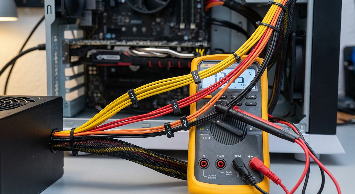
- Identify the pins based on the wiring color codes above. You’ll be focusing on pins for +3.3V (orange), +5V (red), +12V (yellow), and ground (black).
- Insert the black probe into a ground pin (any black wire) while powering on the PSU. Pin 16 is a common choice for this.
- Use the red probe to touch the pin corresponding to the voltage you wish to test (e.g., +12V on a yellow wire).
- Read the voltage displayed on the multimeter. A tolerance of ±5% is generally acceptable.
Common Voltage Outputs
Here’s a quick reference table summarizing the standard voltage outputs and their corresponding pin numbers for a typical ATX connector:
| Wire Color | Voltage Output | Common Pin Number |
|---|---|---|
| Yellow | +12V | 10, 11, 12, 23 |
| Red | +5V | 4, 6, 13, 14 |
| Orange | +3.3V | 1, 2, 3 |
| Purple | +5V Standby | 9 |
| Green | Power On | 16 |
| Black | Ground | Any ground pin |
Interpreting Results
After measuring, you may notice various results ranging from nominal to out-of-spec voltages. Proper interpretation is key:
- If the reading falls within ±5% of the specified voltages, the PSU is generally functioning correctly.
- Values significantly outside this range indicate potential issues with the PSU, such as voltage regulation problems, which could lead to system instability.
- Be aware that a reading of 0V may imply a disconnected PSU or an internal failure.
Safety Considerations
Testing a PSU can pose certain risks, and safety should always be your priority:
- Never test the PSU while it is plugged into the wall and powered on unless you are taking precautions against electrical hazards.
- Always use insulated probes and wear safety goggles to protect your eyes from possible sparks.
- If you are unsure about any step in the process, consult technical resources or seek professional assistance.
Common Misconceptions
Many users believe that if their computer boots up, the PSU is functioning flawlessly. However, intermittent issues can occur, leading to performance degradation over time. Ignoring regular voltage tests can result in unnoticed failures. Additionally, some may think that a visual inspection is sufficient to determine PSU reliability, while in reality, performance inconsistencies often necessitate the use of a multimeter.
Conclusion
With proper knowledge of testing techniques and an understanding of the color codes associated with PSU wires, you can effectively monitor the health of your computer’s power supply. Regular testing helps prevent unexpected failures and prolongs the life of your components. For further similar topics, consider learning about troubleshooting computer hardware issues.
Rotating USBFAQ
Q1: What if the PSU fails during testing?
A1: If the PSU does not turn on or you experience irregular voltages, it is advisable to disconnect it immediately and consult a professional.
Q2: Can I use any multimeter for this test?
A2: Yes, but it’s recommended to use a digital multimeter for accuracy and ease of reading.
Q3: How often should I test my PSU?
A3: Regular testing is suggested, especially if you notice performance issues or before significant upgrades to your system.
Q4: What does a reading of +12.5V indicate?
A4: This is within the acceptable range, as voltages may slightly exceed nominal values due to tolerances.
Q5: Where can I find more information on PSUs?
A5: You can read more about Power Supply Units on Wikipedia or the Corsair Support page for detailed guidance.