Understanding Multimeter Probe Color Codes and Safe Usage
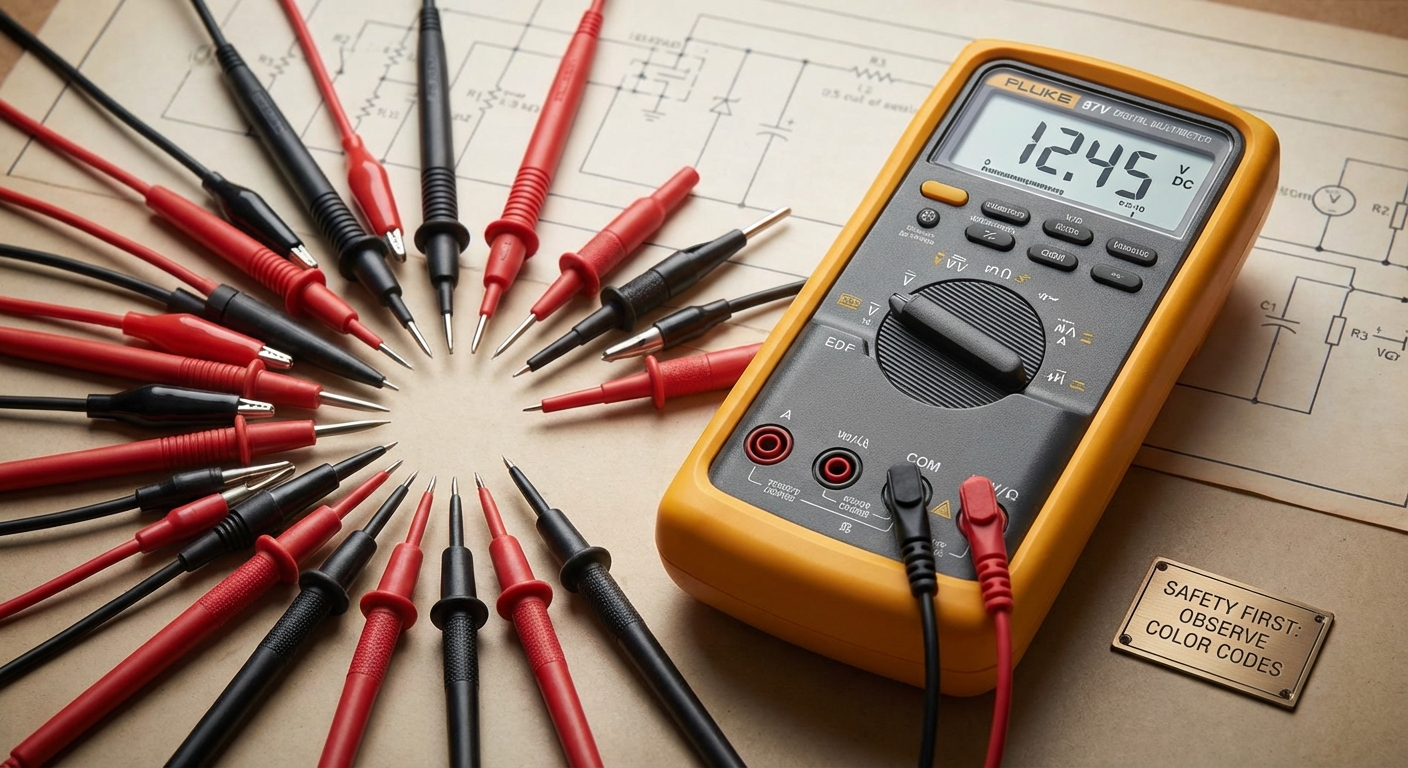
Multimeters are essential tools for electricians, engineers, and DIY enthusiasts, allowing users to measure voltage, current, and resistance in electrical circuits. However, despite their utility, many people remain confused about the correct usage of multimeter probes, especially the significance of color codes associated with them. This article will clarify these color codes and highlight the safety practices necessary for using a multimeter effectively and safely. Understanding this information is crucial as improper use can lead to inaccurate readings or, worse, electrical accidents. A common misconception is that multimeter probes can be interchanged disregarding their color codes, which can lead to confusion and potential hazards. This article will provide a detailed overview of multimeter probe color codes, proper probe usage, safety guidelines, and answers to frequently asked questions to enhance your multimeter skills.
Multimeter Probes: Color Codes and Their Significance
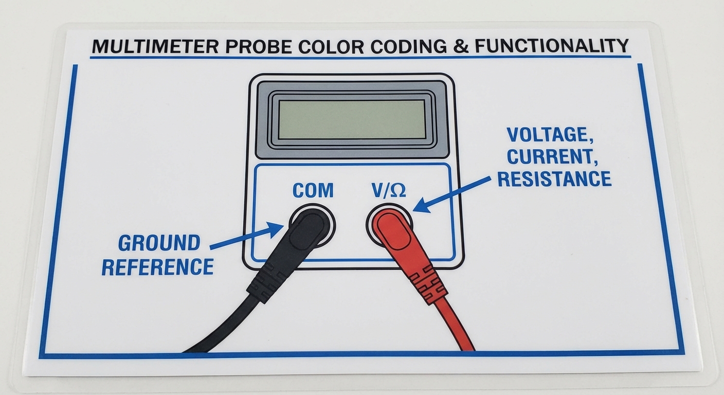
The color of multimeter probes is not merely for aesthetics; it serves essential functional purposes. Here’s what the colors represent:
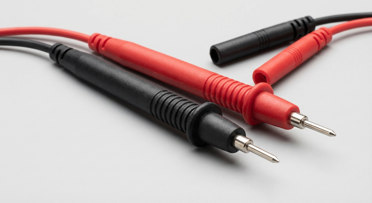
- Black Probe: Always used for the COM (common) port, serving as the ground reference point.
- Red Probe: Connected to the V/Ω port, which is used for measuring voltage (V), current (A), and resistance (Ω). It is important to position the red probe properly based on the measurement being taken.
For accurate multimeter readings, ensure that the black probe is always connected to the COM port and that you are using the red probe appropriately based on the testing parameters. This distinction between probes is critical during measurement operations to avoid misreading and ensuring safety.
How to Use Multimeter Probes Safely
Basic Setup for Measurement
- Identify the measurement you want to take: voltage (AC or DC), current, or resistance.
- Turn the dial on your multimeter to the corresponding setting for the measurement (e.g., Ω for resistance).
- Insert the black probe into the COM port and the red probe into the appropriate VΩ or A port.
- For voltage measurements, touch the probes across the component terminals. For continuity tests, ensure the circuit is de-energized.
Precautionary Measures
Before using your multimeter, consider the following precautions to maintain safety:
You may also like


- Check for Live Circuit: Always ensure the circuit is inactive before connecting the probes unless measuring live voltage.
- Verify Multimeter Range: Ensure your multimeter is set to the correct voltage or current range to avoid device damage.
- Avoid Contact: Be cautious to avoid contact between the probe tips when measuring live voltage, as this can cause short circuits.
- Be Aware of Fluctuations: If readings fluctuate, it indicates a poor connection or that the circuit is live; adjust your probes accordingly.
Understanding Multimeter Symbols
Familiarity with multimeter symbols is equally important as understanding the probes. Below are the most common symbols and their meanings:
| Symbol | Meaning |
|---|---|
| V~ | AC Voltage |
| V⎓ | DC Voltage |
| Ω | Resistance |
| A | Current |
| C | Capacitance |
Understanding these rules will help users determine what they can measure and how best to set up their multimeter for the task.
Preventing Common Multimeter Errors
Common Mistakes When Using Multimeters
Many users, especially beginners, may encounter frequent errors while using a multimeter. Here are common mistakes and how to avoid them:
- Inserting Probes Incorrectly: Always ensure that the black probe is in the COM port and that the red probe is in the correct input for the measurement being taken.
- Failing to Set the Correct Mode: Users often forget to switch the multimeter to the appropriate setting, leading to inaccurate readings or potential damage.
- Measuring Resistance on a Powered Circuit: Always ensure the circuit is de-energized when measuring resistance.
Frequently Asked Questions
Q1: Can I use any multimeter probe for measurements?
A1: No, you should use the black probe for COM and the red probe for V/Ω/A ports, as indicated by their color codes.
Q2: What should I do if the readings on my multimeter are fluctuating?
A2: Fluctuating readings may indicate a poor connection or that the circuit is live. Ensure your probes are making proper contact and the circuit is de-energized if necessary.
Q3: Is it safe to measure resistance on a live circuit?
A3: No, measuring resistance should be done on a de-energized circuit to avoid damage to the multimeter and ensure your safety.
Q4: What does the Ω symbol on my multimeter indicate?
A4: The Ω symbol stands for resistance. It’s used when you want to measure the resistance of a component or circuit.
Q5: Where can I find more detailed information about multimeter usage?
A5: Many manufacturers provide detailed guides on their websites. For example, you can refer to the Fluke support page for helpful resources.
Conclusion
In summary, understanding multimeter probe color codes and safe usage practices is crucial for accurately measuring electrical parameters and ensuring user safety. Always adhere to the established color codes for probes, familiarize yourself with the corresponding multimeter symbols, and follow safety precautions during measurements. With this knowledge, you can confidently utilize a multimeter for various applications, enhancing your electrical skills and projects.
For readers interested in further electrical work, exploring topics related to circuit design and safety equipment is highly recommended.
Rotating USB