Introduction
Chassis intrusion sensors play a critical role in the security of vehicles and sensitive equipment by detecting unauthorized access. These sensors are vital for systems that safeguard against tampering or theft, ensuring peace of mind for both manufacturers and users. The complexity arises when trying to interpret and implement the wire color codes associated with these sensors. A common misconception is that all intrusion sensors follow a standardized color coding system, which can lead to confusion during installation or troubleshooting. In this article, readers will learn about the typical wire color codes used in chassis intrusion sensors, how to interpret them properly, and best practices for ensuring effective installation and functioning of these critical components.
Understanding Chassis Intrusion Sensors
Chassis intrusion sensors are designed to detect physical access to a vehicle or equipment chassis. These sensors are crucial for various applications, including vehicle security systems and server management. Understanding how they work, along with their wiring configurations, is key for anyone involved in the installation or maintenance of these systems.
How Do Chassis Intrusion Sensors Work?
Intrusion sensors typically work by utilizing either mechanical or electromagnetic principles. When the sensor is triggered, it sends a signal to the control unit to alert the users of a breach. Common types of sensors include:
- Inductive sensors, which detect proximity and movement.
- Magnetic switches that close when the chassis is opened, creating a circuit.
- PIR (Passive Infrared) sensors that sense motion within their field.
Common Wire Color Codes
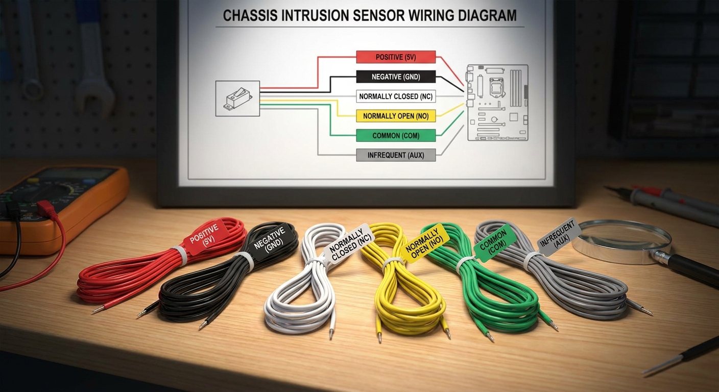
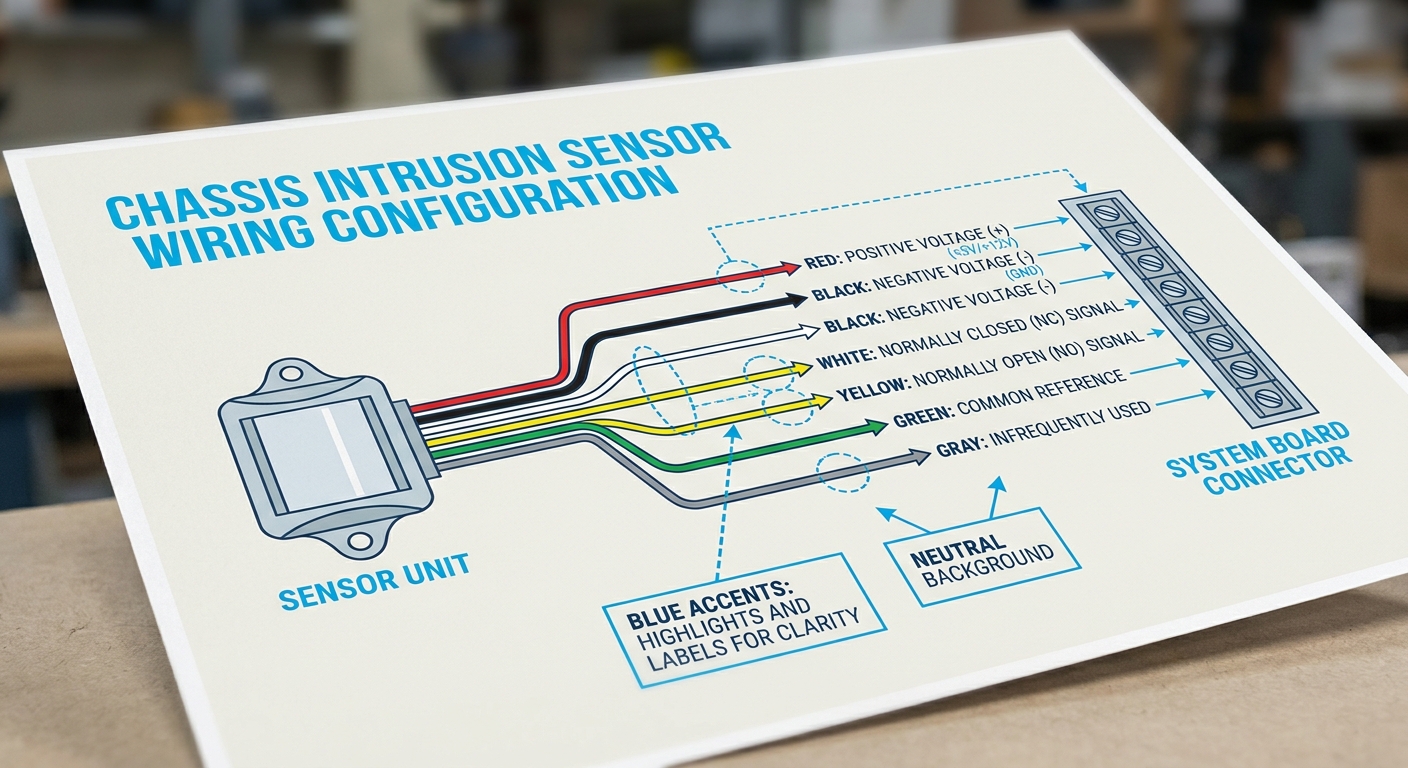
Installation of chassis intrusion sensors involves understanding the specific wire color codes, which can vary between manufacturers. Below is a breakdown of the most commonly encountered color codes for intrusion sensors and their general purposes:
You may also like


| Wire Color | Function |
|---|---|
| Red | Positive voltage supply (+) |
| Black | Negative voltage supply (-) |
| White | Normally Closed (NC) signal |
| Yellow | Zone or normally open (NO) signal |
| Green | Common reference |
| Gray | Infrequently used for specific types |
Additional Notes on Wire Color Codes
A careful review of wiring installation guides from manufacturers highlights variability in wire color codes. For instance, while some guidelines state that positive wires must be red and negative wires black, others diverge. It’s critical to reference both the installation manual and any wiring diagrams provided with your specific intrusion sensor to avoid miswiring.
Tips for Proper Installation
To ensure that intrusion sensors function effectively, follow these installation tips:
- Refer directly to the manufacturer’s wiring diagrams.
- Double-check color codes before making connections.
- Test connections with a multimeter for continuity post-installation.
- Secure all wires to prevent mechanical wear over time.
Testing Chassis Intrusion Sensors
After installation, testing is essential to confirm that the system works as intended. Here are steps to test the installation:
- Ensure the power is off before starting any tests.
- Use a multimeter to check continuity on the various wires, ensuring they connect as per the color codes.
- Power on the system and trigger the sensor manually to ensure it sends an output signal.
- Monitor the response to ensure the alert mechanism is functioning and connected to the central alarm system.
Troubleshooting Common Issues
Despite careful installation, problems may still arise. Here are common issues and their solutions:
- False alarms: Check for environmental factors triggering the sensor or inspect connections for integrity.
- No response: Revisit the wiring connections; a loose wire could disrupt the circuit.
- Inconsistent functioning: Test the voltage supply to ensure the sensor is receiving adequate power.
Frequently Asked Questions
Q: What is the function of the yellow wire in intrusion sensors?
A: The yellow wire typically serves as the normally open (NO) signal, indicating that a circuit is completed when triggered.
Q: Are the wire color codes uniform across all vehicle systems?
A: No, wire color codes can vary by manufacturer and model; always refer to specific installation guidelines.
Q: What tools do I need to install chassis intrusion sensors?
A: Basic tools include wire strippers, crimpers, a multimeter, and electrical tape for securing connections.
Q: How can I ensure optimal sensor performance?
A: Follow installation best practices, ensure wires are correctly connected, and perform regular maintenance checks to avoid wear and exposure to elements.
Q: Can I replace an old sensor with a new one using the same wiring?
A: Typically yes, but verify that the new sensor matches the previous one’s specifications, including wire functions and voltage requirements.
Conclusion
Understanding the wire color codes and proper installation techniques for chassis intrusion sensors is paramount for effective security implementation. By following the guidelines above, users can ensure reliable operation and timely alerts in case of unauthorized access. Proper maintenance and troubleshooting of these sensors are equally important to keep security systems functional. For those looking to further explore security topics, consider researching more on alarm systems or vehicle tracking devices.
Rotating USB