Introduction
Soldering wire color codes are a crucial aspect of electronics repair, providing a standardized visual reference that helps in identifying the purpose of each wire within a circuit. This article addresses the often-overlooked issue of wire color misidentification, a common problem that can lead to incorrect soldering and subsequent electrical failures. Understanding these color codes is vital for hobbyists and professionals alike, as miswiring can not only damage components but also pose safety hazards. Many individuals mistakenly assume that all wires follow a universal color standard; however, coding can vary significantly based on the type of system (e.g., AC vs. DC) and regional regulations. In the following sections, you will learn about the common color codes used in low voltage DC circuits, AC systems, and international standards, as well as practical applications and safety tips for effective soldering.
Understanding Wire Color Codes
Wire color coding is an organized system that assigns specific colors to electrical conductors to indicate their functions. These colors help ensure accurate connections in electronic systems, improving safety and compliance with electrical codes.

The Basics of Color Coding
- Red: Typically used for positive (power) connections in DC circuits.
- Black: Generally denotes negative or ground connections.
- Green: Reserved for earth ground connections.
- Blue and Yellow: Often used in multi-conductor systems for secondary or signal lines.
Low Voltage DC Color Codes
For systems operating at low voltage DC, such as most electronic devices, the following color codes are prevalent:
- Power: Red
- Ground: Black
- Signal: Various colors, often blue or yellow
This simple yet effective coding assists repair technicians in diagnosing and fixing issues quickly while maintaining safety. For instance, a common misconception is that any color can represent power; however, in low voltage situations, you’re likely to encounter the red and black standard.
You may also like


AC Wiring Color Codes
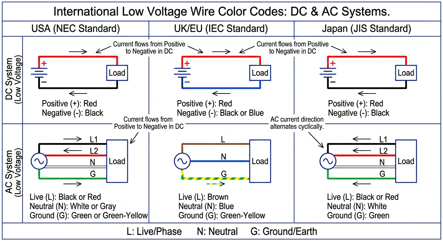
In contrast, alternating current (AC) systems use a different set of color codes based on regional standards. Here’s a basic breakdown:
| Region | Live (Hot) | Neutral | Ground |
|---|---|---|---|
| USA | Black or Red | White | Green or Bare Copper |
| UK/EU | Brown | Blue | Green/Yellow |
| Japan | Black or Red | White | Green |
Awareness of these differences is essential for safety, especially when performing multistage repairs or installations involving international components.
Application of Color Codes in Electronics Repair
Whether you are a beginner or an experienced technician, applying wire color codes correctly is vital in maintaining functional and safe electronic systems.
Steps for Proper Soldering
- Identify the wires’ colors to understand their roles.
- Strip approximately 1/2 inch of insulation from the end of each wire.
- Twist the exposed ends together for better conductivity.
- Heat the soldering iron and apply solder to the joint for a solid connection.
- Allow the joint to cool before insulating it with electrical tape or heat shrink tubing.
Proper soldering techniques, combined with an understanding of color codes, significantly reduce the risk of errors during repairs. Many failures arise not from poor technique but from incorrect wire identification.
Common Misconceptions About Wire Colors
- All red is positive: While this is often true for DC, it can vary based on the application.
- Black is always negative: In some AC applications, black can be a hot wire.
- Color codes are universal: There are regional differences that must be considered.
Safety Considerations
Adhering to wire color codes is not merely advisable; it’s necessary for avoiding hazardous situations. Some key safety tips include:
- Always double-check the wire color codes against local regulations.
- Utilize a multimeter to verify voltages before working on live circuits.
- Encapsulate any exposed wire ends with electrical tape to prevent accidental contact.
International Standards for Wire Color Coding
IEC Standards
The International Electrotechnical Commission (IEC) has set standards that differ from the U.S. NEC codes. The IEC defined color codes for both single-phase and three-phase systems:
- Single-phase: Brown (live), Blue (neutral), and Green/Yellow (earth).
- Three-phase: Brown, Black, Grey for live connections; Blue for neutral and Green/Yellow for earth.
Effect on Global Electronics
Understanding these international standards is increasingly essential as global manufacturing and cross-border repairs become more common. Familiarity with multiple color schemes can enhance the effectiveness of repairs and installations across various systems.
FAQ
Q1: What does a bare copper wire indicate?
A1: Bare copper wires are used for grounding purposes.
Q2: Can a wire’s function change based on its color?
A2: Yes, the function of a wire can depend on the specific application and regional standards, so color coding should always be verified.
Q3: Are there color codes for low-voltage AC systems?
A3: Yes, low-voltage AC systems often follow different color codes; always consult local standards for clarification.
Q4: Why is it important to use the correct color coding in repairs?
A4: Using the wrong color code can lead to dangerous miswirings, potentially damaging equipment or causing safety hazards.
Q5: How often should wiring be checked for color coding compliance?
A5: It is good practice to verify wiring color coding during routine maintenance and inspections for compliance with current safety standards.
Conclusion
In summary, understanding soldering wire color codes is crucial for anyone involved in electronics repair. Familiarity with these codes can prevent costly errors and enhance safety. As technology and practices evolve, staying informed on wire color conventions and standards will continue to be paramount in the field of electronics.
Related topics include soldering techniques and electrical safety practices.
Rotating USB