Understanding USB Type-C Pinout: A Gateway to Enhanced Connectivity
The advent of the USB Type-C connector has revolutionized the landscape of data transfer and power delivery, making it a crucial component in modern technology. This article addresses the critical question: What exactly is the pinout configuration of USB Type-C, and how does it function? As devices become increasingly interconnected, understanding USB Type-C’s design is essential for developers, manufacturers, and users alike, enabling them to leverage its full capabilities. A common misconception is that USB Type-C serves merely as a standard charging port; however, it is much more, including data transfer at speeds up to 80 Gbps and supporting high power delivery of up to 240W. In this article, readers will learn about the pinout structure and functions of the USB Type-C connector, its operation, and its implications for future technology innovations.
How USB Type-C Works
USB Type-C is a reversible connector that facilitates various functionalities, including high-speed data transfer, video output, and power delivery. At the heart of this technology lies its intricate pinout structure, which consists of 24 pins responsible for different tasks.
The 24 Pins of USB Type-C
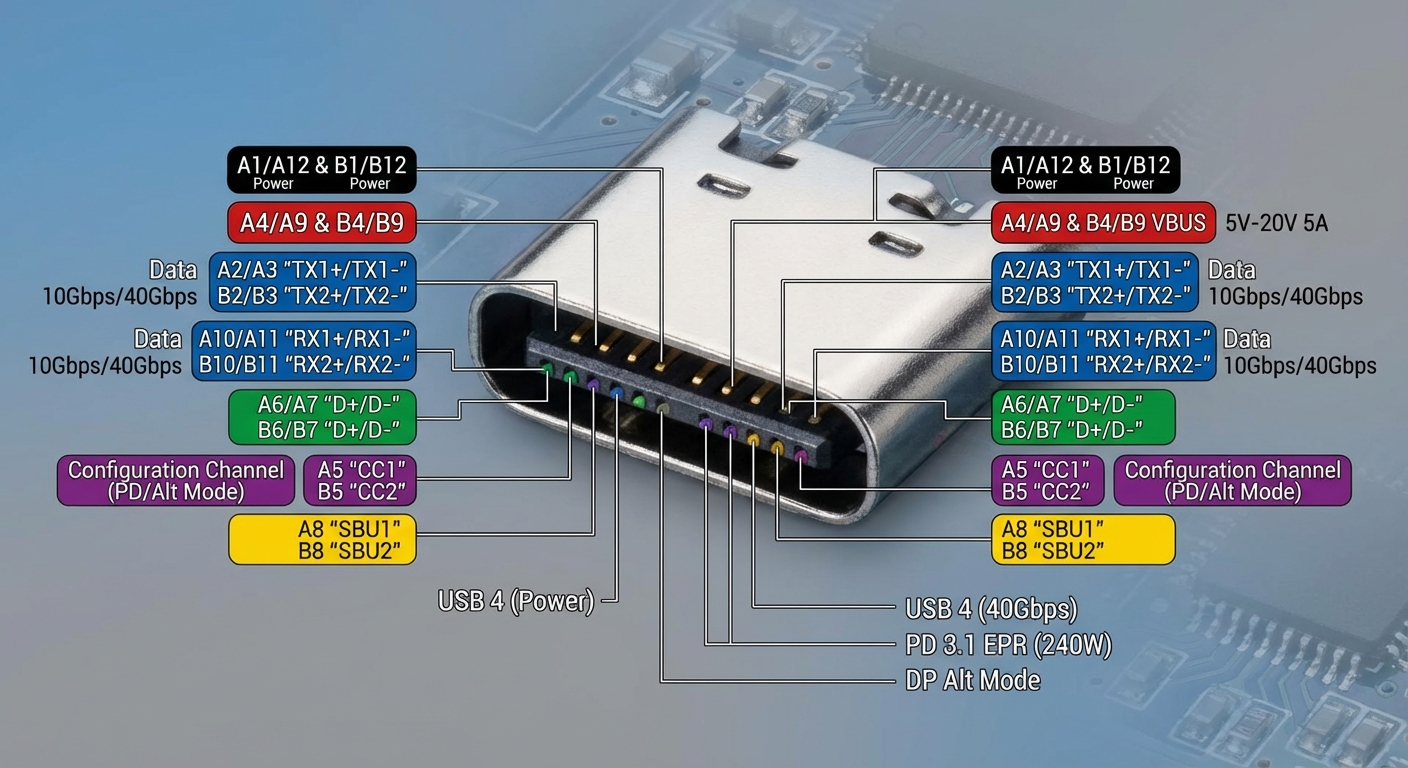
- Power Pins: These include the VBUS and GND pins. VBUS delivers up to 20V and 5A, allowing for power delivery up to 100W under the USB Power Delivery specification.
- Data Pins: USB Type-C features SuperSpeed data Pins referenced as TX/RX pairs, which can facilitate USB 3.x standards and reach speeds up to 20Gbps. Depending on the device and cable used, these can also be employed for Alternate Modes (like HDMI or DisplayPort).
- USB 2.0 Pins: The D+/D- pins are retained for backward compatibility with USB 2.0 devices.
- Configuration Channel (CC) Pins: These pins manage cable orientation, power delivery negotiations, and Role Detection. Only two of the four CC pins are used in any configuration, depending on the connector orientation.
- Sideband Use (SBU) Pins: These pins provide additional signaling capabilities, which may be employed for features such as audio or other auxiliary data.
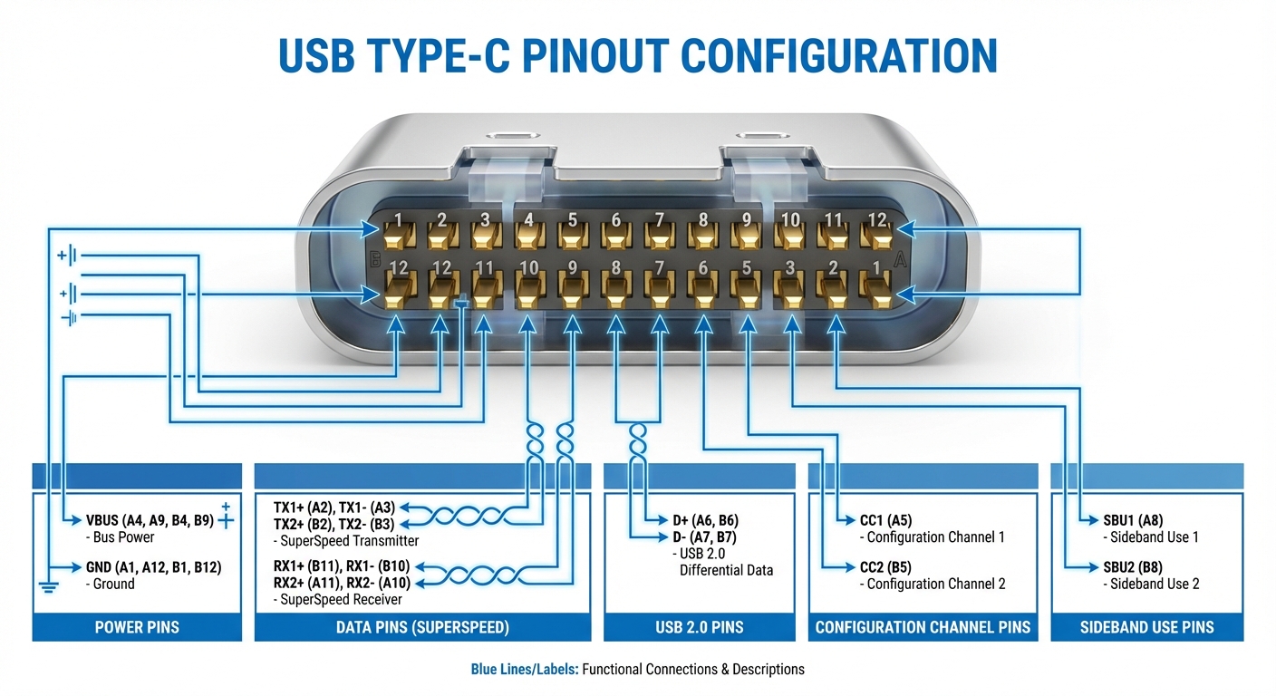
Pinout Diagram Simplified
The diagram below illustrates the USB Type-C pinout, detailing the function of each pin and their arrangement:
| Pin Number | Pin Name | Function |
|---|---|---|
| 1 | GND | Ground |
| 2 | VBUS | Power Delivery |
| 3 | CC1 | Configuration Channel 1 |
| 4 | DD+ | USB 2.0 Data |
| 5 | DD- | USB 2.0 Data |
| 6 | CC2 | Configuration Channel 2 |
| 7 | TX1 | SuperSpeed Transmit 1 |
| 8 | RX1 | SuperSpeed Receive 1 |
| 9 | TX2 | SuperSpeed Transmit 2 |
| 10 | RX2 | SuperSpeed Receive 2 |
| 11-24 | VCONN, SBU1/SBU2 | Used for auxiliary functions and power management |
USB Power Delivery: Capabilities and Negotiation
One of the most significant innovations that come with USB Type-C is the USB Power Delivery (PD) protocol. This enables devices to negotiate the power level required based on their needs, accommodating a wide range of devices, from smartphones to laptops. Power levels can be adapted, allowing devices to charge faster while also ensuring safety and efficiency.
You may also like


How Negotiation Works
When a USB Type-C cable is connected, the Configuration Channel (CC) pins play a crucial role in initiating the Power Delivery negotiation. The connected devices can detect their roles (i.e., source or sink) and establish the appropriate power level. This capability means that manufacturers can optimize charging times and enable devices to communicate their power needs dynamically.
Common Misconceptions About USB Type-C
Despite its growing popularity, several misconceptions persist regarding USB Type-C:
- Misconception 1: All USB-C cables support high-speed data transfer.
- Misconception 2: USB Type-C is only for charging phones and not for laptops or other devices.
- Misconception 3: USB Type-C is synonymous with USB 3.1; in reality, it encompasses various versions, including USB 2.0 and USB4.
Technical Implementation and Considerations
To effectively utilize the USB Type-C interface, it is often advisable to employ dedicated USB-C port controller chips. These chips integrate various functions, including CC pin management, power FET control, and PD protocol handling. This integration not only simplifies the design but also enhances the reliability and performance of devices leveraging USB Type-C. The USB Type-C Cable and Connector Specification Release 2.2 outlines pin behaviors and mechanical requirements in detail, essential for manufacturers looking to implement this technology effectively.
Frequently Asked Questions
What types of devices can use USB Type-C?
USB Type-C connectors are used in various devices, including smartphones, laptops, tablets, and peripheral devices like keyboards and mice.
Can USB Type-C support video output?
Yes, USB Type-C supports Alternate Modes, which allow video output through standards like HDMI and DisplayPort.
Are all USB-C cables created equal?
No, USB-C cables can differ in functionality. Some may support only USB 2.0 data speeds, while others can handle USB 3.x speeds or provide power delivery.
How do I know if my device supports USB Power Delivery?
Check the manufacturer’s specifications or documentation for your device. If it mentions USB Power Delivery, your device supports this feature.
Can USB Type-C be used for data and charging simultaneously?
Yes, USB Type-C is designed to support simultaneous data transfer and power delivery, making it a versatile connector for modern devices.
Conclusion
In summary, the USB Type-C pinout is a groundbreaking development that integrates multiple functionalities into a single connector, streamlining connectivity while increasing power delivery and data transfer capabilities. Understanding its pinout and configurations is vital for anyone involved in technology, from engineers to everyday users. As technology continues to evolve, the relevance of USB Type-C is likely to expand even further, paving the way for innovative solutions in device connectivity.
For more information on USB standards, check out the USB Wikipedia page. For technical support and detailed specifications, refer to the USB Implementers Forum.
Rotating USB