Understanding SATA Power Cable Wire Color Codes and Pinout
The Serial ATA (SATA) power cable is an essential component in modern computing, providing adequate power supply to storage devices like hard drives and solid-state drives (SSDs). However, many individuals face challenges when configuring or troubleshooting these connections due to misunderstandings about wire color codes and pinout layouts. This article aims to clarify these specifications to aid users in identifying and successfully connecting SATA power cables.
It is common for users to mix up the functions of various wires because of their similar appearances, leading to equipment malfunctions or even damage. By dissecting the SATA power connector’s wiring and offering clear color codes and pin designs, readers will learn exactly what each wire supports, ensuring safe and effective usage.
How SATA Power Connectors Work
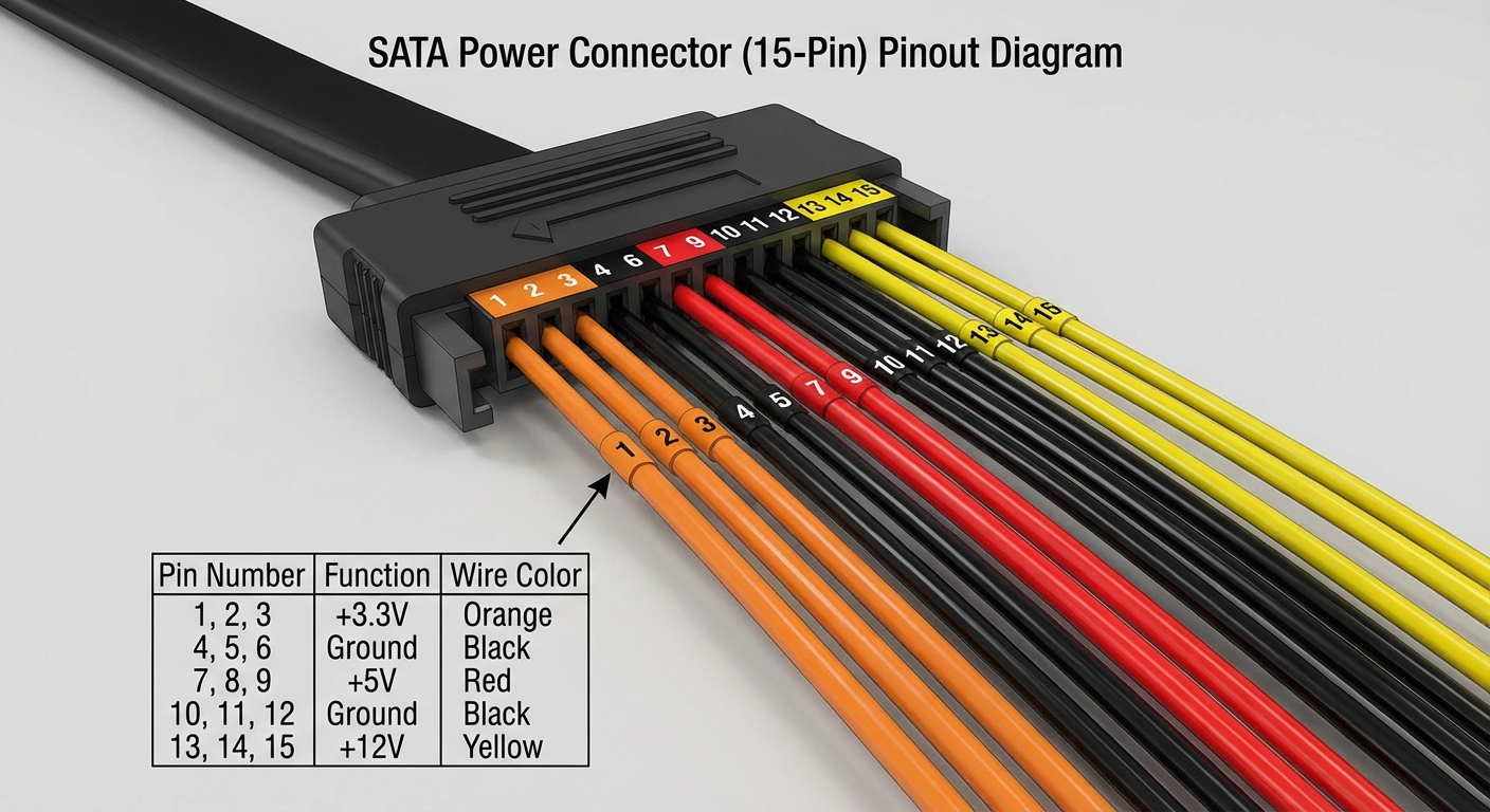
The SATA power connector features a 15-pin layout designed to deliver various voltage levels, supplying power to drives in a standardized manner. Understanding this layout is paramount for successful installation and maintenance of storage devices.
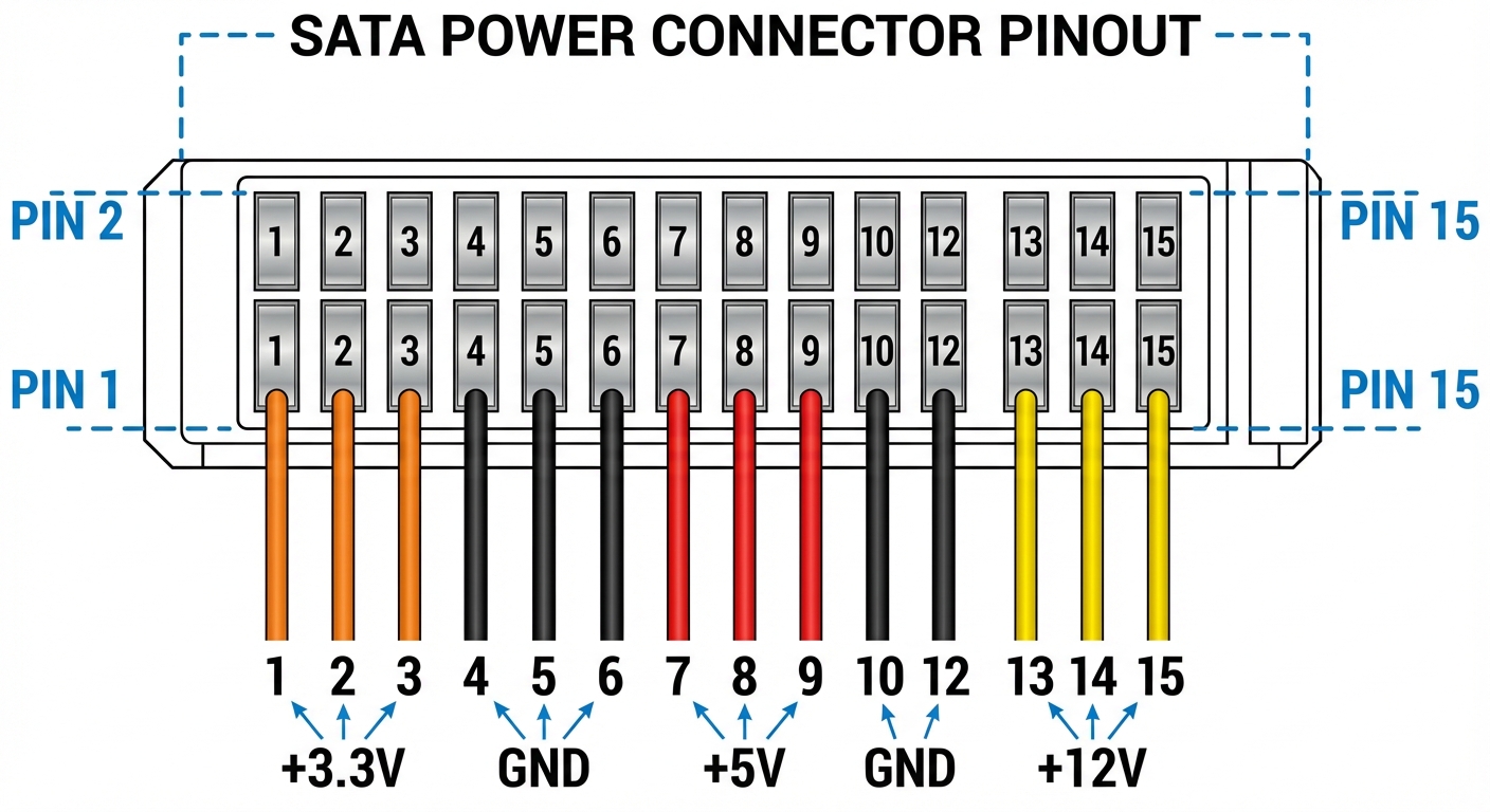
Pinout Layout of the SATA Power Connector
| Pin Number | Function | Color Code | Description |
|---|---|---|---|
| 1 | +3.3VDC | Orange | Provides 3.3 Volts |
| 2 | +3.3VDC | Orange | Provides 3.3 Volts |
| 3 | +3.3VDC | Orange | Used for devices that require 3.3V |
| 4 | Ground | Black | Common ground for all voltages |
| 5 | Ground | Black | Common ground for all voltages |
| 6 | +5VDC | Red | Provides 5 Volts |
| 7 | Ground | Black | Common ground for all voltages |
| 8 | Ground | Black | Common ground for all voltages |
| 9 | +12VDC | Yellow | Provides 12 Volts |
| 10 | Ground | Black | Common ground for all voltages |
| 11 | Ground | Black | Common ground for all voltages |
| 12 | +12VDC | Yellow | Allows devices to draw 12V as needed |
| 13 | +12VDC | Yellow | Used for higher power devices |
| 14 | Reserved | – | Future use |
| 15 | Reserved | – | Future use |
SATA Power Connectors: Colors and Functions
The color coding in SATA power cables is consistent and represents the voltage supply each wire delivers:
You may also like


- Orange: Supplies 3.3 Volts
- Black: Ground, serving as the common return path for power
- Red: Provides 5 Volts
- Yellow: Supplies 12 Volts
This standardized color scheme is critical for users to correctly identify which wires to connect, ensuring compatibility between the SATA power cable and the devices it powers.
Common Issues with SATA Power Connection
With the standardized layout, users may still encounter issues during setup. Here are some common problems and troubleshooting steps:
Incorrect Connections
- Ensure that the colors of the wires match the respective pins on the SATA power connector.
- Double-check that each wire is seated correctly in the pin slots to avoid loose connections.
Incompatibility with Older Devices
Some older devices might require power connectors that differ from the SATA standard. In such cases, users should consider:
- Using adapter cables to convert from SATA to the required older format.
- Verifying if the device manual specifies power connection requirements.
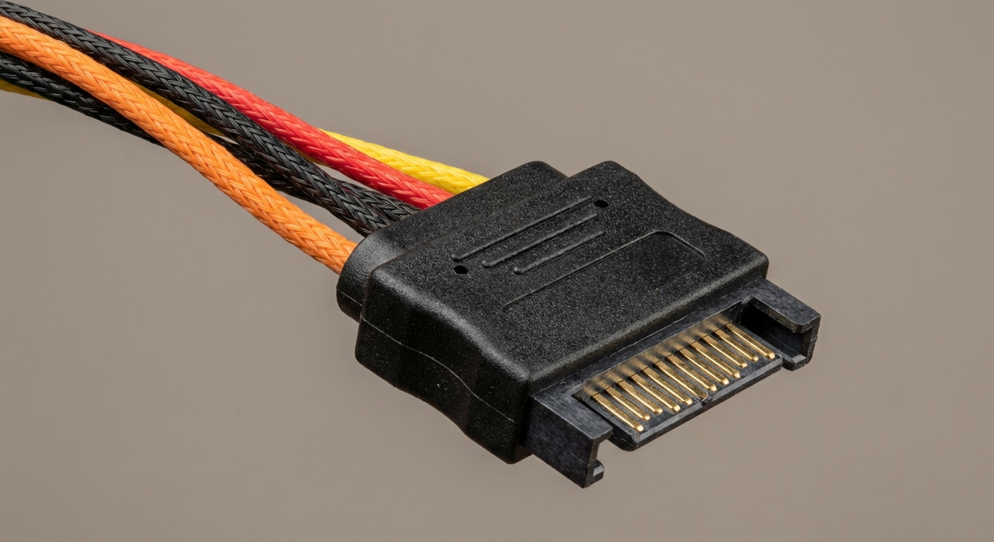
SATA Power Connector Specifications and Applications
SATA power connectors are predominantly used in modern hard drives, SSDs, and optical drives. Their design not only provides reliable power but also streamlines cable management with smaller, more efficient connectors than older standards like the Molex connector.
Final Remarks on SATA Power Connectors
Understanding the SATA power cable wire color codes and pinouts can significantly enhance user experience while setting up or troubleshooting storage devices. Clarity on this topic helps ensure that users have a foundational understanding necessary to work confidently with their technology.
Frequently Asked Questions
Q: What does the orange wire in a SATA power connector do?
A: The orange wire supplies +3.3 Volts of power.
Q: How many total pins are there in a SATA power connector?
A: There are a total of 15 pins in a SATA power connector.
Q: What happens if I connect a SATA power cable incorrectly?
A: Incorrect connections can lead to device malfunction or damage.
Q: Are SATA power connectors compatible with older devices?
A: Not necessarily; some older devices may require different power connectors.
Q: What colors indicate ground connections in a SATA power connector?
A: The black wires indicate ground connections.
Conclusion
This article presented an in-depth look at SATA power cable wire color codes and pinout specifications, empowering readers with the knowledge needed to make correct installations and troubleshoot effectively. For those delving deeper into computer hardware, understanding topics like data cables and internal power management can be equally beneficial.
Rotating USB