Introduction
Understanding resistor color codes is essential for anyone engaged in motherboard repair, as these components play a critical role in the functionality of electronic devices. Color bands on resistors indicate their resistance values, tolerances, and other specifications, enabling technicians to accurately replace or repair components. However, many individuals encounter difficulty reading these color codes, which can lead to improper replacements and flawed repairs.
This article addresses the common challenges in interpreting resistor color codes and the significance of accurate identification in motherboard repairs. Misreading these codes not only hampers repair efforts but can also lead to further damages, complicating the troubleshooting process. Through this article, readers will learn how resistor color codes work, the different band configurations, and how to effectively identify resistor values.
The Basics of Resistor Color Codes
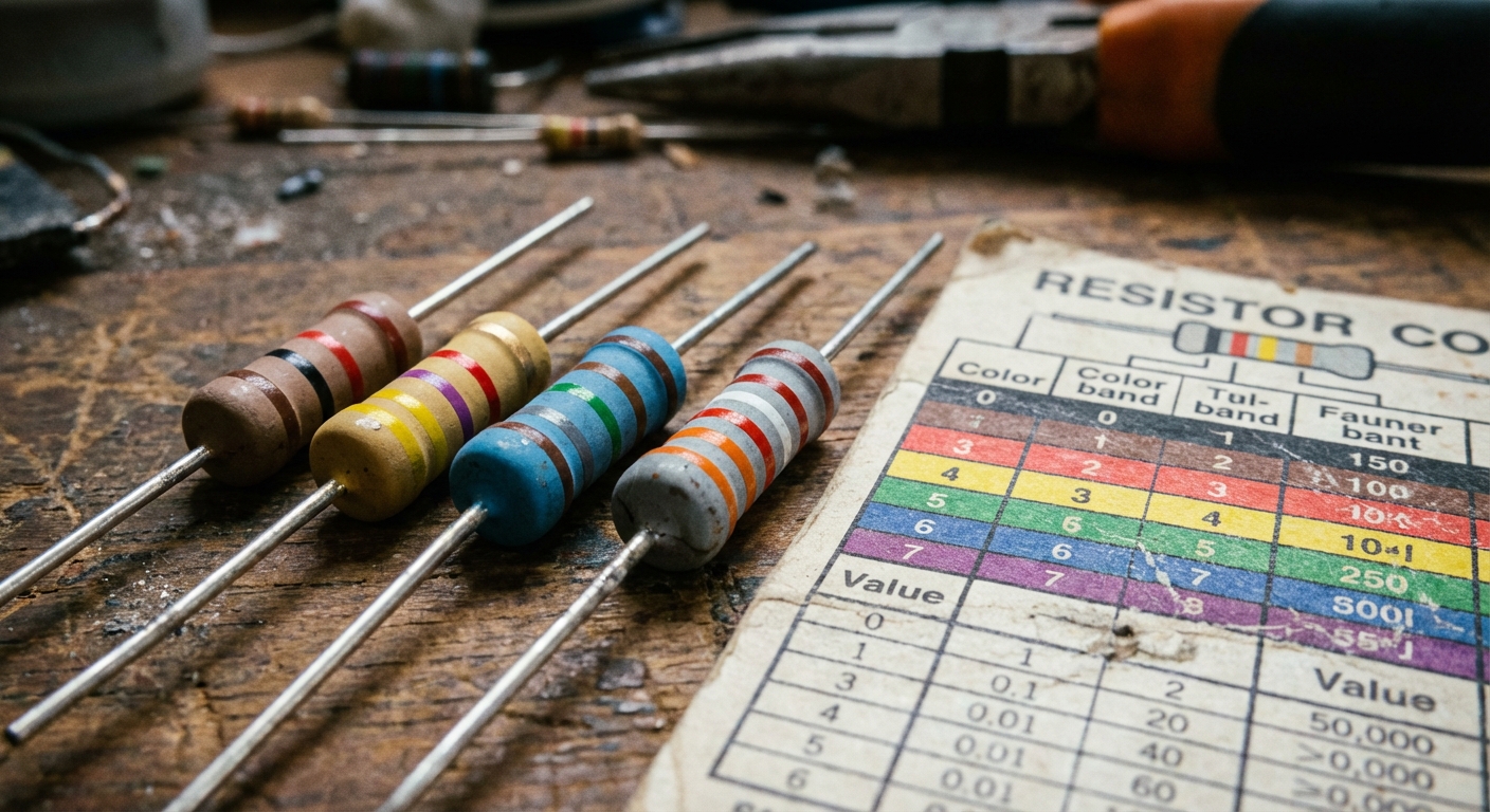
Resistor values are conveyed through a system of colored bands painted on the component’s body. Each color corresponds to a specific number, which translates into a resistance value. Typically, resistors can feature 3, 4, 5, or 6 color bands. The common practice is to read the colors from left to right, with the last band indicating the tolerance.
Understanding Band Configurations
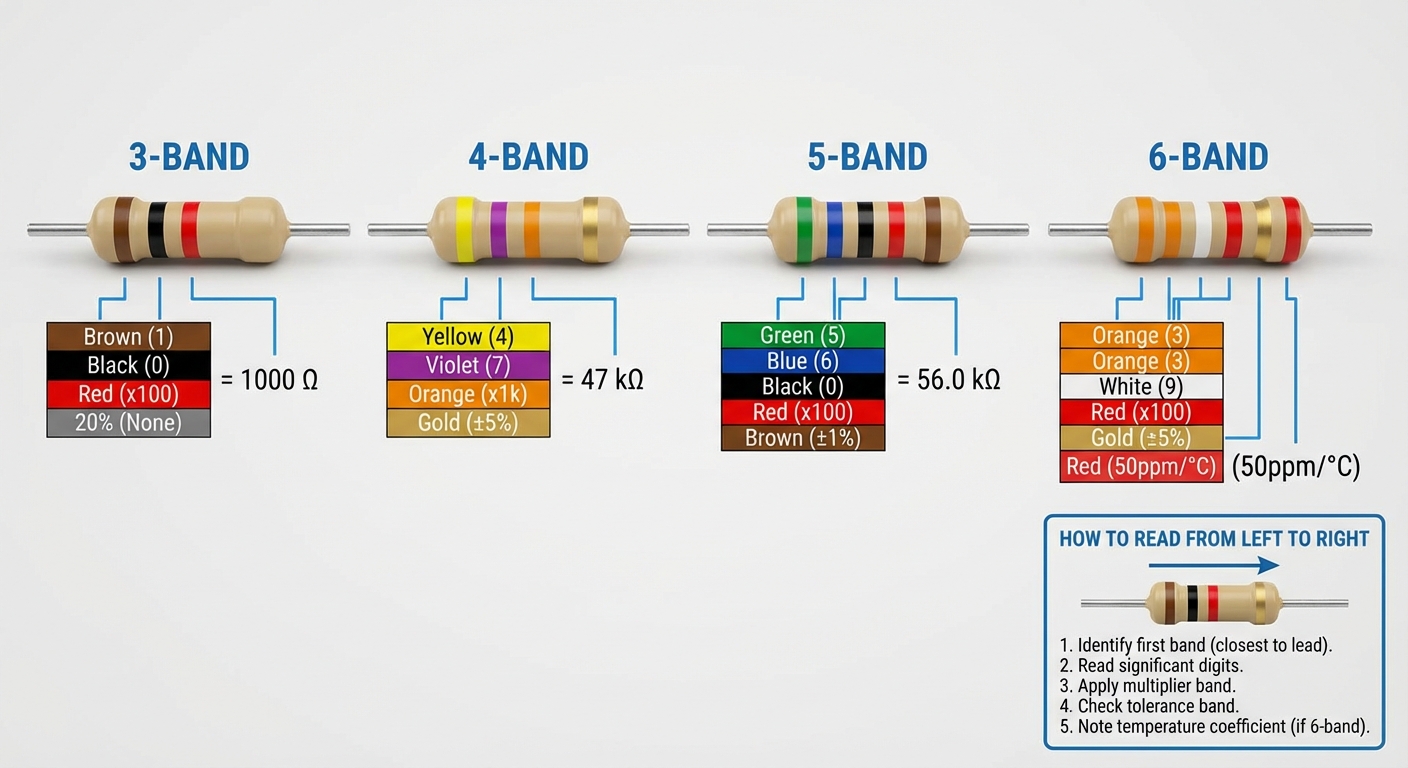
- 3-Band Resistors: These include two significant digits and a multiplier. For instance, a resistor with bands of red, violet, and yellow translates to 2 (red), 7 (violet), and a multiplier of 10^4, equating to a total resistance of 270,000 ohms (Ω).
- 4-Band Resistors: Similar to 3-band, but with one additional band for tolerance. For example, a resistor showing brown, green, red, and gold bands indicates 1 (brown), 5 (green), a multiplier of 10^2, and a tolerance of ±5%.
- 5-Band Resistors: These provide more precision, incorporating three significant digits, a multiplier, and tolerance. An example is a resistor with bands of blue, black, orange, orange, and brown translating to a resistance of 600,000 Ω with ±1% tolerance.
- 6-Band Resistors: Typically used for precision applications, these include the temperature coefficient in addition to the other values. A resistor marked with colors includes a tolerance value that indicates reliability.
How Color Codes Work
The color code system dates back to the 1930s, developed to facilitate quick and accurate identification of resistor specifications. Each color corresponds to a numeric value according to a standardized table.
You may also like


| Color | Value |
|---|---|
| Black | 0 |
| Brown | 1 |
| Red | 2 |
| Orange | 3 |
| Yellow | 4 |
| Green | 5 |
| Blue | 6 |
| Violet | 7 |
| Gray | 8 |
| White | 9 |
| Gold | Tolerance: ±5% |
| Silver | Tolerance: ±10% |
Common Misconceptions
One prevalent misconception is that all resistors follow the same band formatting. While the majority adhere to the standard, variations do exist, especially in historical or specialized resistors. For example, high-precision resistors may use additional bands to indicate tighter tolerances, leading to confusion among novices.
Testing and Identifying Resistors
When working on motherboard repairs, it’s paramount to accurately identify resistor values for effective troubleshooting.
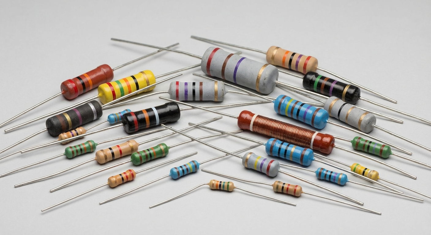
- Visually Inspect the Resistor: Check the color bands carefully. Note that lighting may affect visibility, so use a consistent light source.
- Use a Multimeter: If unsure of the resistor’s color coding, using a multimeter to test its resistance directly provides the most accurate measurement.
- Cross-Reference with Color Code Charts: Keep a color code chart on hand for quick reference. Various online resources provide charts that clarify any ambiguities.
Resources for Further Learning
For those wanting to delve deeper into the world of electronic components and color codes, reliable resources such as Wikipedia can offer comprehensive information. Suppliers like TE Connectivity provide additional insights and technical support about their products.
FAQ
Q1: How can I tell if a resistor is damaged?
A1: Look for physical signs of damage such as discoloration, bulging, or a broken body. Use a multimeter to check for continuity or resistance values that deviate substantially from their marked value.
Q2: What is the significance of tolerance in resistors?
A2: Tolerance indicates how much the resistor’s actual resistance can vary from its labeled value. For example, a resistor with ±5% tolerance could have a resistance that is 5% above or below its stated value.
Q3: Are there special considerations for soldering resistors on a motherboard?
A3: Yes, it’s important to ensure that the soldering temperature does not exceed the component’s rated specification. Moreover, ensure to avoid overheating, which could damage the resistor.
Q4: Can resistor color codes change between manufacturers?
A4: While the color code system is generally standardized, different manufacturers may have variations in resistor design or additional markings. Always refer to manufacturer specifications when in doubt.
Q5: What tools are essential for troubleshooting motherboard resistors?
A5: A multimeter is crucial for measuring resistance and checking continuity. Additionally, having a magnifying glass and a color code chart can aid in identifying resistor values accurately.
Conclusion
Mastering resistor color codes is not only beneficial but essential for effective motherboard repair. Understanding how to read these codes facilitates accurate component replacement, ultimately saving time and reducing repair costs. For those interested in electronic repair, gaining familiarity with these essential components paves the way for deeper knowledge in the field.
Rotating USB