Understanding Power Button and Reset Switch Wire Color Codes
When assembling or troubleshooting a PC, understanding the power button and reset switch wire color codes is crucial. A common problem many builders face is the uncertainty surrounding which wire connects to which motherboard pins—specifically, identifying the correct connections for the power switch, reset switch, and various LEDs. This knowledge matters because improper connections can prevent a machine from powering on, leading to unnecessary frustration. A prevalent misconception is that all wire colors are standardized; however, various manufacturers may use different color codes, making it vital for builders to consult the documentation for their specific components. In this article, readers will learn about the typical wire color codes, how to interpret them effectively, and the importance of correctly identifying ground and power connections.
Power Switch and Reset Switch Overview
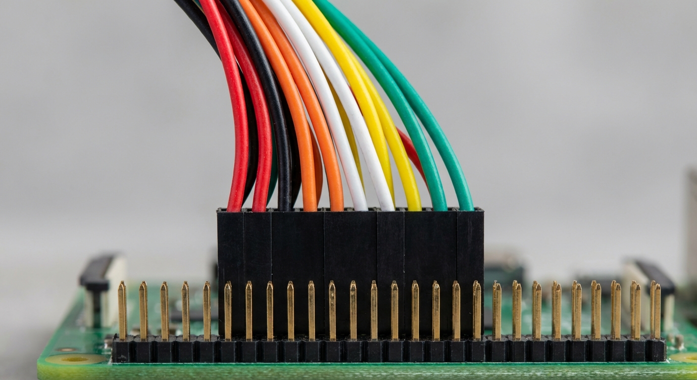
The power button and reset switch are essential components of a computer system’s front panel. They allow users to power on or reset the machine conveniently. Each of these components is typically accompanied by two wires: one for the ground and one for the connection to the motherboard. Understanding how these work is essential for anyone performing hardware installations or upgrades.
Wire Color Codes
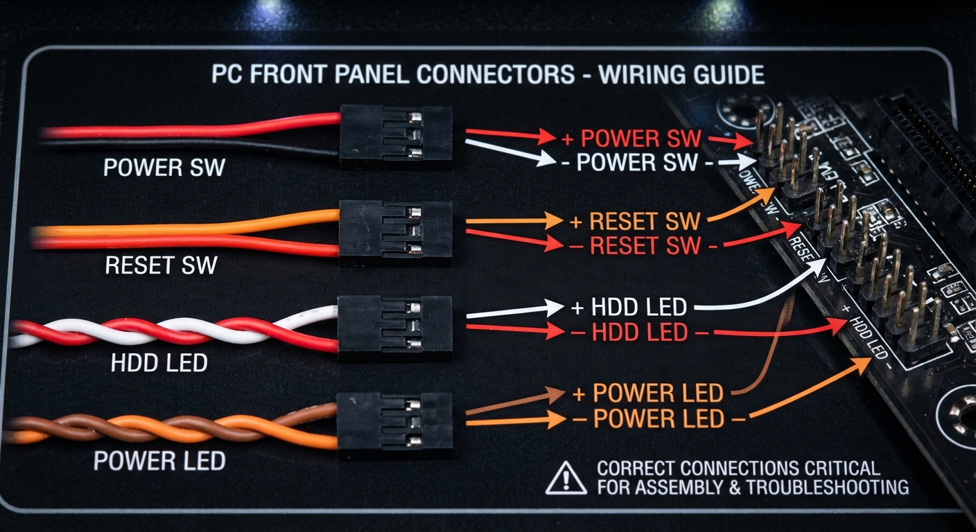
Understanding wire color codes is critical when connecting front panel components to the motherboard. The most common pairings of wire colors based on findings from the sources include:
- Power Switch: Often red and black or blue and black
- Reset Switch: Commonly orange and red or white and green
- Power LED: Typically white and red
- HDD LED: May feature brown and orange or similar combinations
It’s important to note that these colors are not universally applied, so it is essential to refer to the manual associated with your specific motherboard or case.
You may also like

Understanding Voltage and Ground
By electrical convention, negative wires are usually colored black while positive wires can vary in color but are generally red. As confirmed by sources, the negative or ground wire often has a white stripe or markings, which can help in identifying it. Here’s a breakdown of common conventions:
- Black: Ground/Negative
- Red: Positive
- White: Generally Negative
- Colored Stripes or other colors: Positive depending on context
The ground connection is crucial for device safety, preventing issues related to electrical shorts.
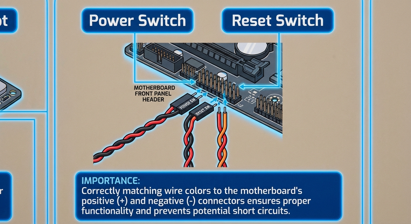
Connecting Wires to the Motherboard
When connecting the wires, follow these general steps:
- Identify the header pins on your motherboard; these are typically marked as PWR, RESET, HDD, etc.
- Match the wire colors from the front panel to the designated header pins on the motherboard.
- Ensure the black wire is connected to the ground pin while the colored wire should connect to the appropriate signal pin.
- Double-check the documentation for your specific motherboard for confirmation of pin assignments.
For example, on some motherboards, you may find the pin layout such that the power switch connects to the first set of pins, while the reset switch may connect to a subsequent set. This is where knowing the specific wire color codes and their functions becomes vital.
Common Troubleshooting Tips
After connecting your wires, if the power button doesn’t seem to function correctly, consider the following troubleshooting steps:
- Check wire connections for firmness; loose connections may prevent functionality.
- Verify that the correct pins on the motherboard are utilized as per your manual.
- Ensure that the power supply unit (PSU) is supplying adequate power.
- Test the power button separately by shorting the power pins with a screwdriver to eliminate button failure as a potential issue.
These steps can help pinpoint issues related to the power and reset switches during the assembly or maintenance of a PC.
Conclusion
Understanding wire color codes for power buttons and reset switches is crucial for any PC builder or technician. Proper identification of these wires ensures a seamless connection to the motherboard and contributes to overall system functionality. By knowing common color conventions and following established connection practices, users can avoid potential pitfalls. As this topic intertwines with many areas of PC assembly, further exploration into related topics such as cable management and motherboard layouts can enhance overall knowledge.
Rotating USB