Understanding PC Case Front Panel Header Color Codes
Building or upgrading a PC can be a rewarding endeavor, but it often presents unique challenges, particularly when connecting the front panel headers from the computer case to the motherboard. One common issue is the confusion surrounding color codes for these headers. While it should be a straightforward task, inconsistency among manufacturers leads to misunderstandings about what each color represents, potentially resulting in incorrect connections. Understanding these color codes is crucial because improper connections can prevent basic functions like powering on the PC or indicate issues through status LEDs. In this article, we’ll delve into the common color codes used for front panel headers, the significance of each connection, and how to troubleshoot any issues that may arise during installation, ensuring your PC runs smoothly.
How PC Front Panel Headers Work
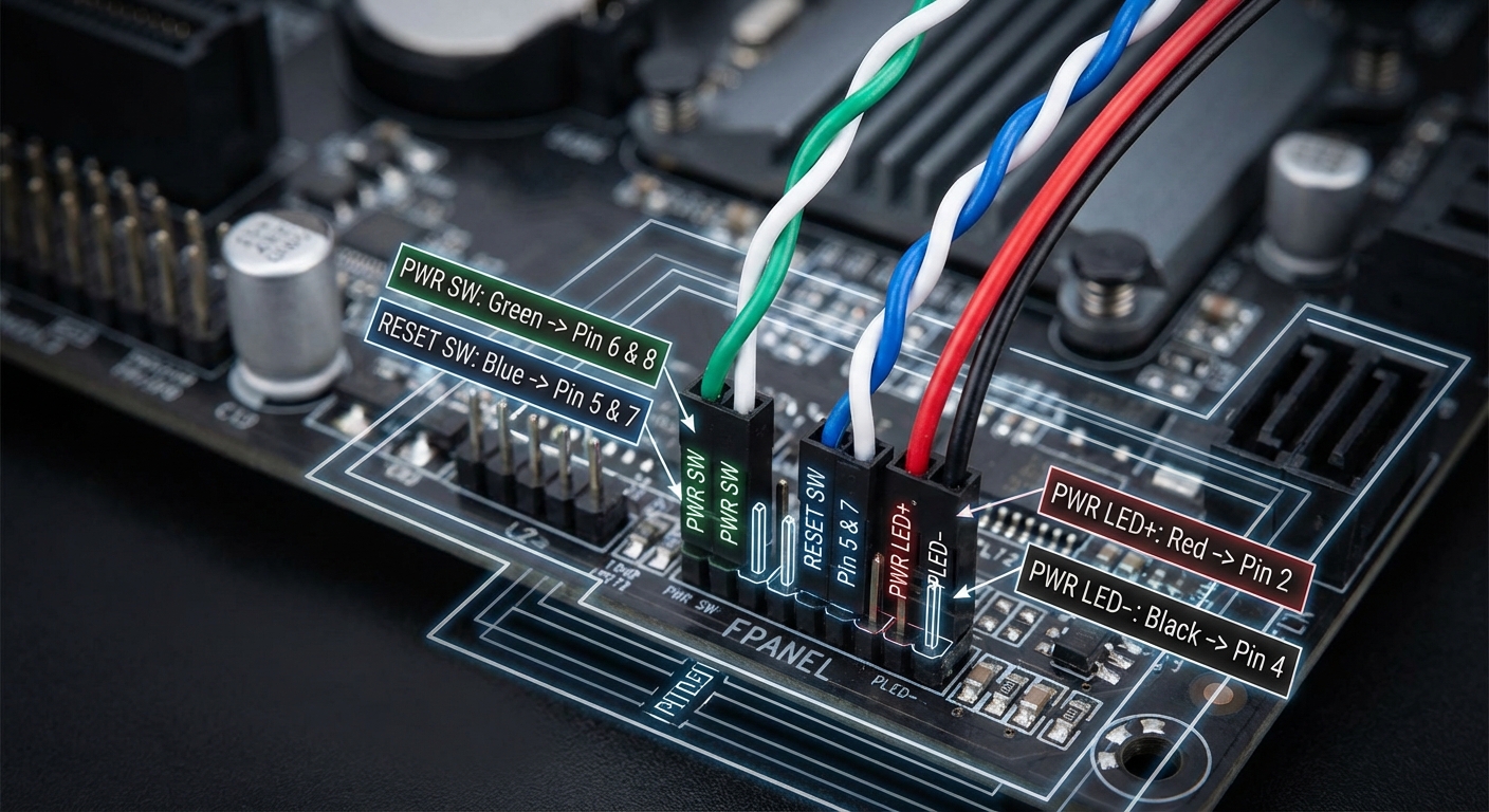
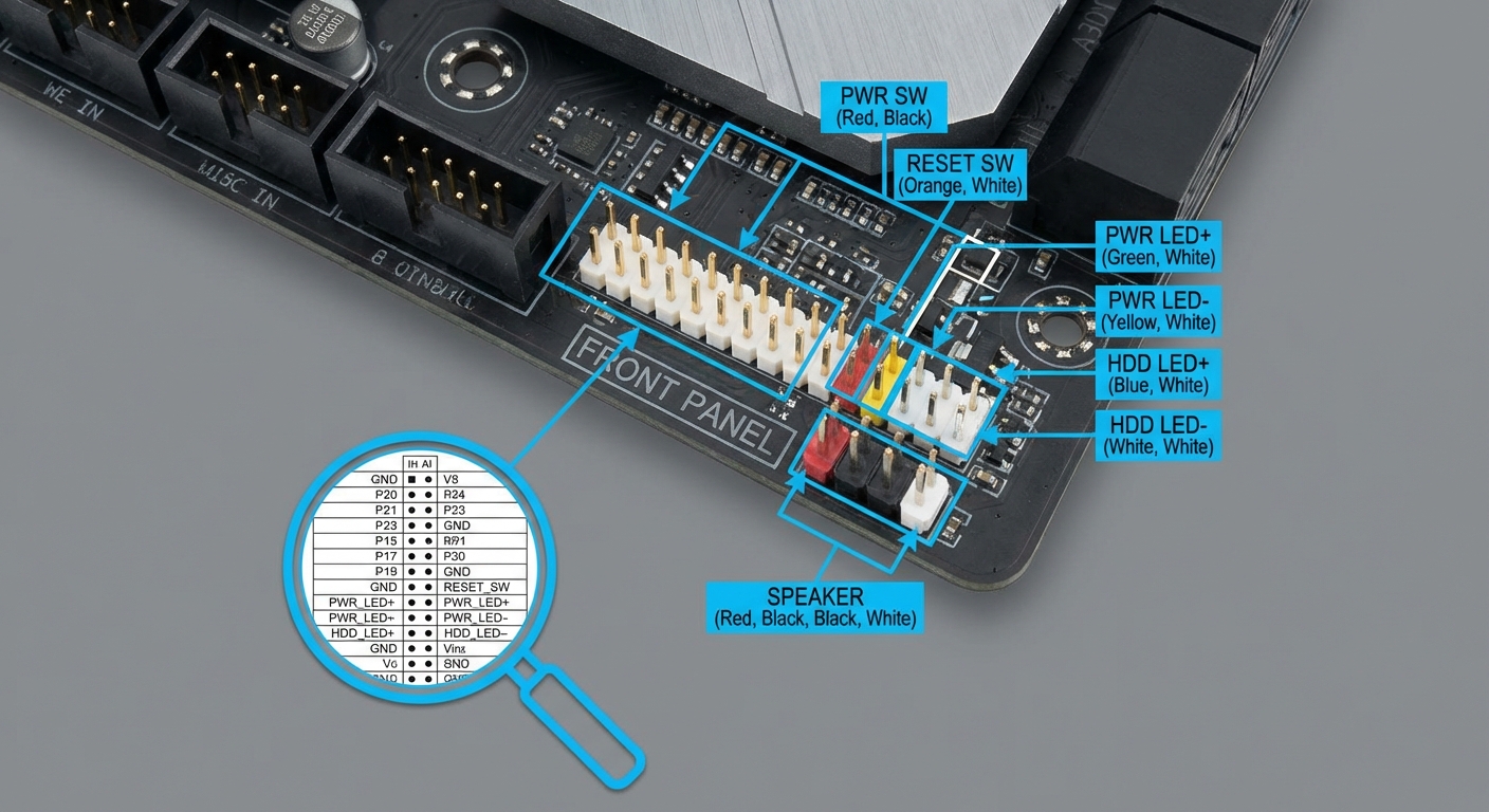
The front panel header is a small collection of pins located on the motherboard that connects to various buttons and lights on the case. These connections facilitate critical functions such as power, reset, and HDD activity indicators. The association between specific pins and their corresponding functions often varies by manufacturer, making it essential to consult your motherboard manual before connecting these headers.
Common Front Panel Connectors
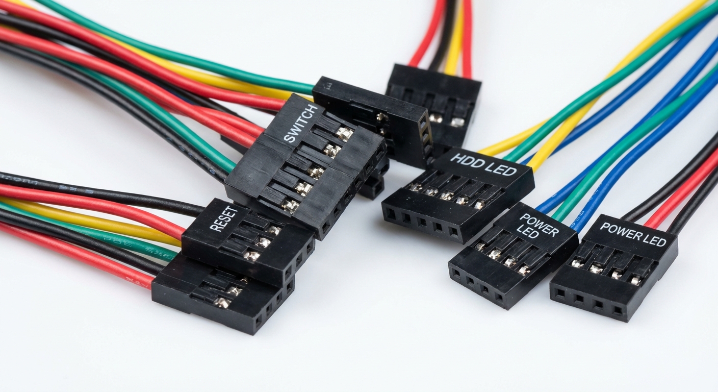
Here are the most frequently encountered front panel connectors:
- PWR SW: Power switch button to turn the PC on or off.
- RESET SW: Reset button to reboot the system.
- PWR LED: Power LED indicator showing system status.
- HDD LED: Hard drive activity LED indicating read/write operations.
- SPEAKER: Internal speaker for beep codes during startup.
Understanding Color Codes
Most manufacturers do not adhere to strict color code standards for front panel connectors. However, some common themes tend to emerge:
You may also like

- Red: Generally represents positive (+) connections.
- Black: Typically indicates ground (-) connections.
Despite these common associations, it is crucial to consult the documentation that accompanies your motherboard or PC case, as they can vary significantly from one manufacturer to another.
Pin Layouts and Connection Schematics
To further clarify the connection process, below is a general overview of the pin configurations for various motherboard brands. While the layouts may vary, the primary functions remain consistent.
| Function | Pin Number | Common Color |
|---|---|---|
| PWR LED + | 1 | Red |
| PWR LED – | 2 | Black |
| HDD LED + | 3 | Yellow |
| HDD LED – | 4 | Black |
| PWR SW | 5 | Green |
| RESET SW | 6 | Blue |
This table should serve as a guideline, but you must verify the exact configuration with your motherboard’s manual.
Troubleshooting Common Issues
Diagnosing Connection Problems
If your system does not power on or if the LEDs are not functioning correctly after connection, consider the following diagnostic steps:
- Verify connections: Ensure that each cable is firmly attached and correctly oriented.
- Check the manual: Cross-reference the connections with the motherboard manual to check for any discrepancies.
- Inspect color coding: Make sure you are following the appropriate color codes, though they may differ by manufacturer.
- Power supply test: Verify that the power supply is functioning properly and that it is supplying power to the motherboard.
- Use a multimeter: If available, check the voltage output to ensure correct signals are reaching the LEDs and switches.
FAQ
What do the colors on the front panel connectors mean?
The colors typically indicate positive and negative connections, with red often being positive (+) and black denoting ground (-). However, always refer to your specific motherboard’s manual for clarification.
Why does my case have different color connectors?
Different manufacturers may not follow the same color coding system, which is why it’s essential to consult the documentation for your motherboard and case.
How can I find the correct pin layout for my motherboard?
The best way to find the pin layout is by referring to the motherboard manual, which usually includes a diagram of the front panel header.
What if the LED indicators do not work after installation?
Check the connections to ensure they are properly seated and oriented correctly. If problems persist, consult the motherboard manual for detailed troubleshooting.
Are there universal front panel header standards?
There is no universal standard between manufacturers; however, Intel has a commonly used layout that many brands mimic, but variations do exist.
Conclusion
Understanding the color codes and connections for PC front panel headers is essential to successfully assembling a computer. Always refer to the specific documentation for your components to avoid confusion and potential malfunctions. For any builders or enthusiasts, mastering these connections is a critical skill that enhances overall experience and confidence in PC building.
For further guidance on PC assembly, consider exploring topics on motherboard features or case compatibility.
Rotating USB