Introduction
Understanding capacitor polarity and markings is a critical skill for anyone working with electronic components. Capacitors, essential in circuits for energy storage and filtering, can be confusing due to their various types and the associated markings that determine their proper usage. Many enthusiasts and professionals alike question how to correctly identify positive and negative terminals on capacitors, particularly electrolytic and tantalum types, which commonly feature polarity indicators. Misinterpretation of these markings can lead to circuit failure or damage, making this knowledge vital for successful circuit design and repair. In this article, we will dive into the different methods of identifying capacitor polarity, decode the various markings found on capacitors, and clarify common misconceptions regarding capacitor color codes and symbols, enhancing your ability to choose the right components for your projects.
Understanding Capacitor Polarity
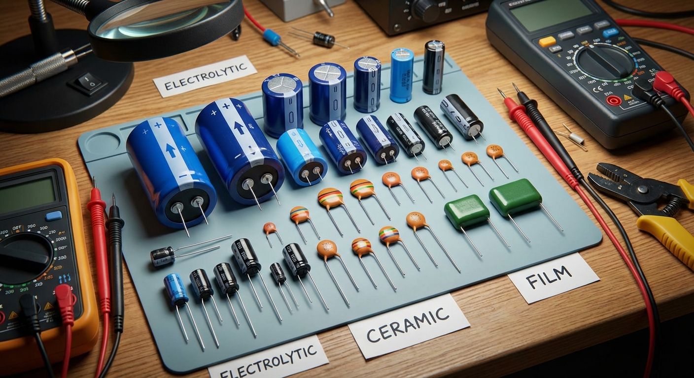
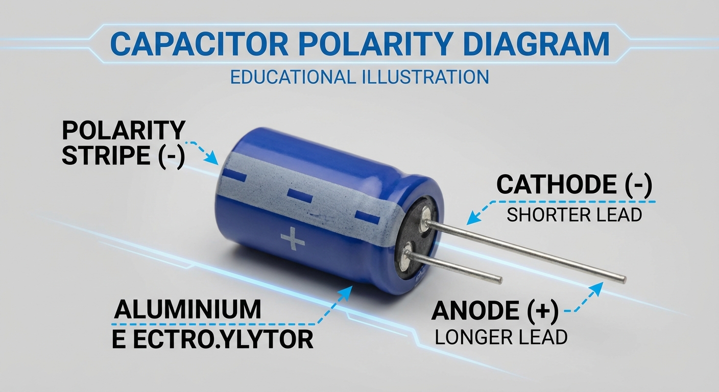
Capacitors are polarized components, meaning they have a positive terminal and a negative terminal. Understanding how to identify these terminals is crucial for the correct installation and functioning of the capacitor within a circuit.
Identifying Polarity Markings
- Lead Length: In many cases, the length of the leads accompanying a capacitor can indicate polarity. The positive lead (anode) is often longer than the negative lead (cathode).
- Body Markings: Capacitors will often have markings on their body. The negative side is typically marked with a stripe or a negative (-) symbol. The positive terminal may be identified by a plus (+) sign.
- Capacitor Type: Different types of capacitors have varying identification methods. For example, tantalum capacitors tend to feature a bar or indentation indicating the positive terminal, while electrolytic capacitors adhere more commonly to the lead length or stripe marking.
Capacitor Color Codes
Color codes are used to identify the capacitance value, tolerance, and voltage rating of capacitors, much like resistors. Understanding how to read these codes is essential for selecting the right capacitor for a specific application.
Reading Capacitor Color Codes
Color codes on capacitors can be read using the following guidelines:
You may also like


- Each color corresponds to a number that represents significant digits and factors in capacitance value calculations.
- The first two bands indicate significant digits; the third band is the multiplier.
- A fourth band may indicate tolerance, while a fifth band, if present, usually represents voltage rating.
Example of a Color Code
For instance, a capacitor with bands colored orange, orange, and brown would represent the capacitance value of 33 x 10^1, which equals 330 pF with a tolerance of ±1%.
Capacitor Value Codes and Markings
In addition to color codes, capacitors may also be marked with alphanumeric codes that indicate their values and specifications.
Common Value Markings
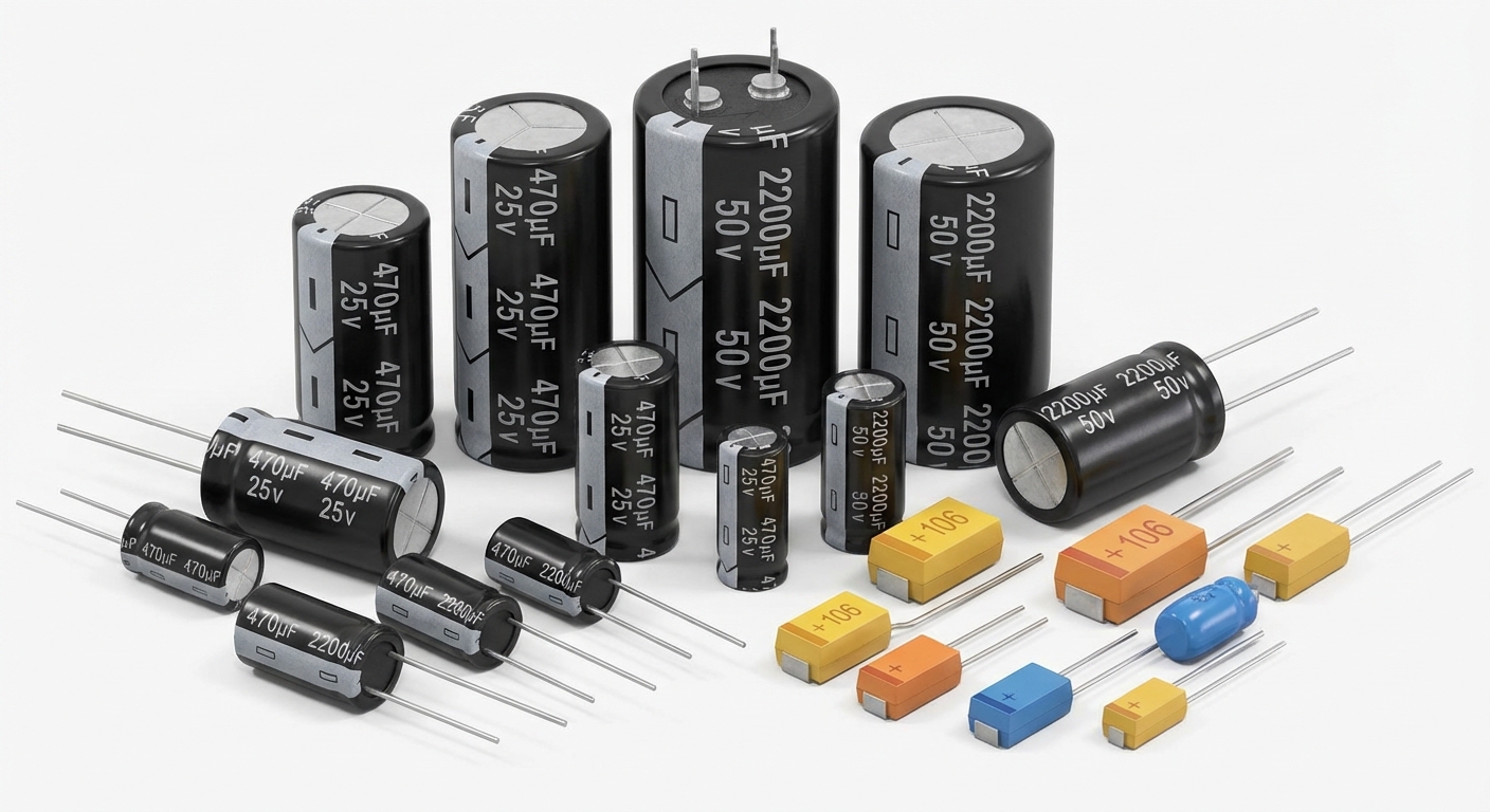
Electrolytic and tantalum capacitors commonly utilize different markings:
- Electrolytic Capacitors: Can have their values printed outright, such as “100μF,” indicating capacitance in microfarads.
- SMD Tantalum Capacitors: Might use a three-digit code followed by a letter indicating tolerance. For instance, a code of “105” indicates a capacitance of 1μF.
- Ceramic Capacitors: May use shorthand notations such as “10n” representing 10 nanofarads.
Common Misconceptions
Some common misconceptions regarding capacitor polarity and markings include:
- All Capacitors Are Polarized: Not all capacitors, such as ceramic and film capacitors, are polarized. It’s important to check specifications before installation.
- Values Can Be Assumed: Many assume that capacitor markings are intuitive; however, reading the specific codes is crucial to avoid mistakes.
- Color Code Reading Is Universal: Misinterpretations can occur as color codes may differ slightly based on manufacturer; always check the manufacturer’s datasheet when in doubt.
Capacitor Testing and Troubleshooting
Understanding how to troubleshoot capacitors and test their functionality is a valuable skill.
Diagnostic Steps for Identifying Capacitor Issues
- Visually inspect the capacitor for any physical signs of damage, such as bloating or leakage.
- Use a multimeter to measure capacitance. Ensure the multimeter is set to the appropriate range.
- If capacitance is measured below the rated value or not measurable, the capacitor may be faulty and require replacement.
FAQs
What does capacitor polarity mean?
Capacitor polarity refers to the designated positive and negative terminals of polarized capacitors, which must be connected correctly to work properly.
How can I identify the positive terminal of a capacitor?
The positive terminal is often identified by being the longer lead, a plus (+) marking, or a colored band along the side of the capacitor.
Are all capacitors polarized?
No, not all capacitors are polarized. Ceramic and film capacitors, for instance, can be non-polarized and can be connected in either direction in a circuit.
How do I read a capacitor’s color code?
To read a capacitor’s color code, identify the first two bands as significant digits, the third as a multiplier, and check for additional bands indicating tolerance and voltage rating.
Why is it important to observe capacitor polarity?
Observing capacitor polarity is crucial because connecting a polarized capacitor in reverse can damage the capacitor and the circuit, potentially causing failure or hazards.
Conclusion
Understanding capacitor polarity markings and color codes is essential for anyone working with electronic components. Proper identification and installation not only ensure the functionality of circuits but also prevent potential damage to components. As you enhance your knowledge of these critical aspects, you’ll be better equipped to select the right capacitors for your projects and troubleshoot effectively when issues arise.
Rotating USB